
Industry
Production, gathering and processing facilities, where structural scope ranges from new process areas to modifications across producing fields.
Onshore energy facilities depend on a large volume of steel and concrete structures that have to be coordinated with piping, equipment and electrical layouts.
Our senior team's experience covers pipe racks and pipe bridges, process and access platforms, equipment supports and plant buildings on onshore oil and gas developments, in new process areas and on producing fields.
Civil and structural production work commonly commissioned for these facilities. Each item is delivered through one of our six services and scoped to the approved project inputs.
Onshore structures rarely stand alone. Racks carry piping and cable trays, platforms wrap equipment, and foundations follow vendor data that changes late. Documentation is organised around those interfaces so revisions are absorbed in a controlled way.
The technical services most often commissioned for onshore oil & gas facilities work, and what each contributes.
 S01Civil & Structural Engineering DraftingGA and layout drawings for racks, platforms and foundations.View service
 S023D Structural Modelling & Plant Model SupportStructural models inside the project's plant environment.View service
 S03Structural Steel Detailing & Fabrication DocumentationShop and erection drawings for racks, platforms and supports.View service
 S04Reinforced Concrete & Rebar DetailingFoundation, pedestal and equipment-base reinforcement.View service
 S05Brownfield Structural Modifications & As-Built DocumentationModification packages on producing facilities.View service
Typical inputs & constraints
Scope & responsibility
We produce drawings, models, detailing and documentation from approved design information. Design decisions, calculations and approvals remain with the responsible engineer.
General arrangement and framing plans, sections and elevations showing tiers, bents and longitudinal bracing, plus anchor-bolt and foundation layouts. Once connections are approved, the detailing stage adds assembly, single-part and erection drawings with member and bolt lists. Pipe-support attachments, cable-tray brackets and access platforms are usually listed separately so their revisions can be tracked against the piping layout.
Foundation and pedestal drawings note the vendor-data revision they are based on. When certified vendor data arrives, anchor-bolt patterns, pocket sizes and grout levels are checked against it, and the affected drawings, bar bending schedules and MTO are reissued together under the next revision with clouded changes.
Yes, where verified site information is supplied: survey records, laser-scan point clouds, photographs and existing drawings marked up by the site team. Existing conditions that cannot be confirmed from those records are flagged on the drawings as hold points for site verification rather than assumed.
Owner and EPC specifications generally govern, with steel and concrete design codes as specified by the responsible designer.
The scope of work records the applicable standards and editions for each package. A reference to a standard does not imply design verification or certification.
How standards are appliedClient / EPC / asset owner
Client, EPC and Owner Standards and Project Specifications
AISC
Specification for Structural Steel Buildings
ACI
Building Code Requirements for Structural Concrete
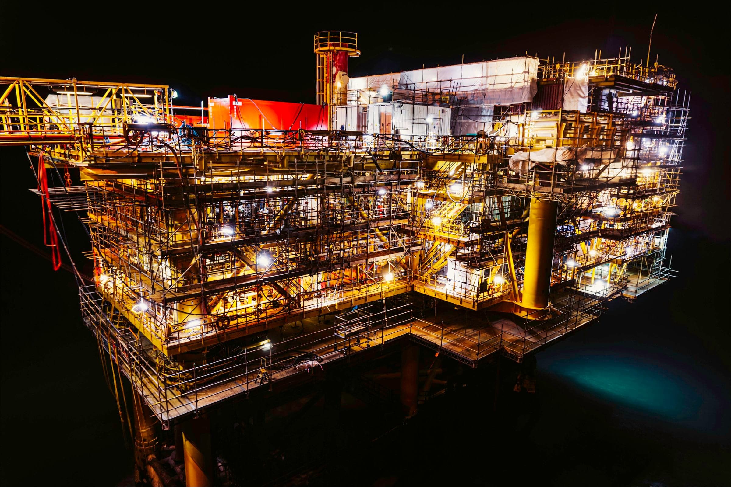
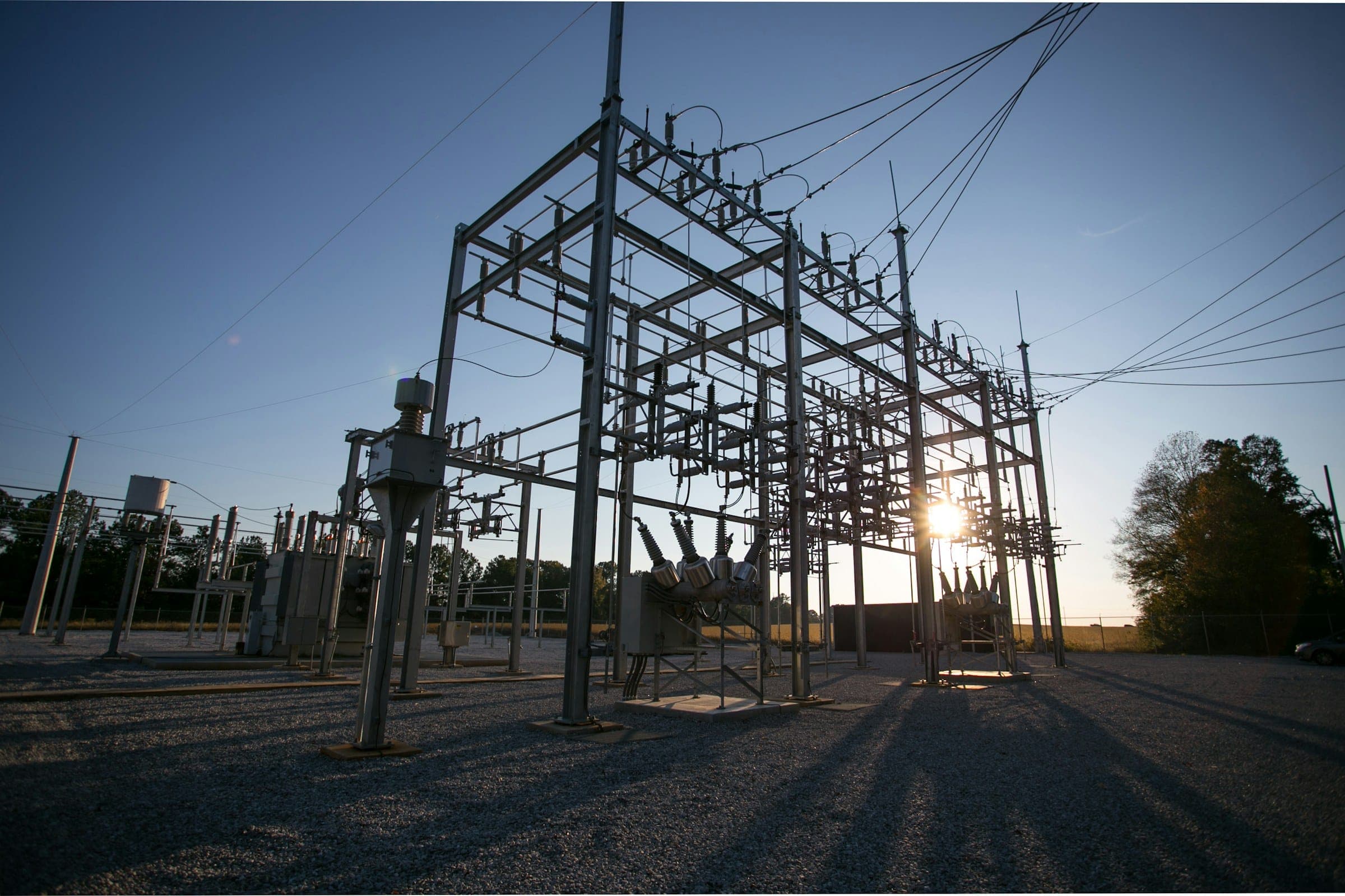
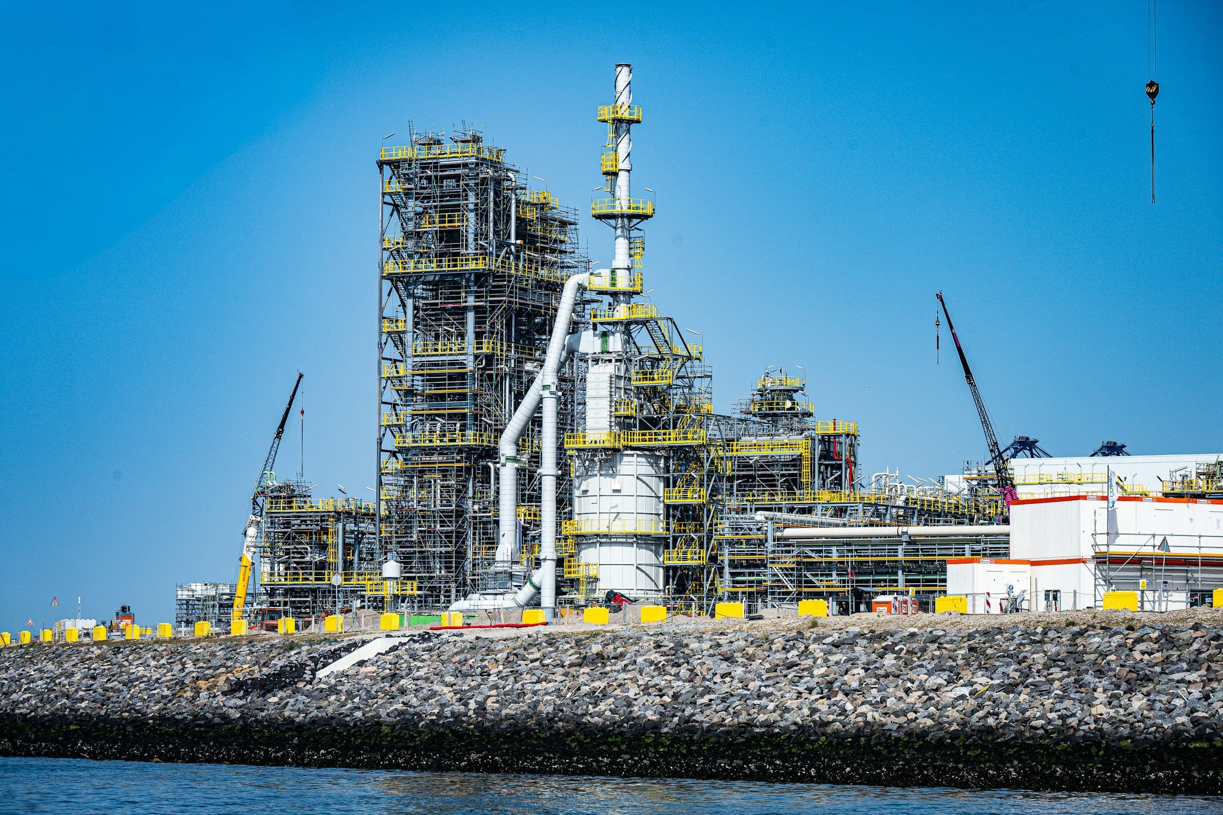
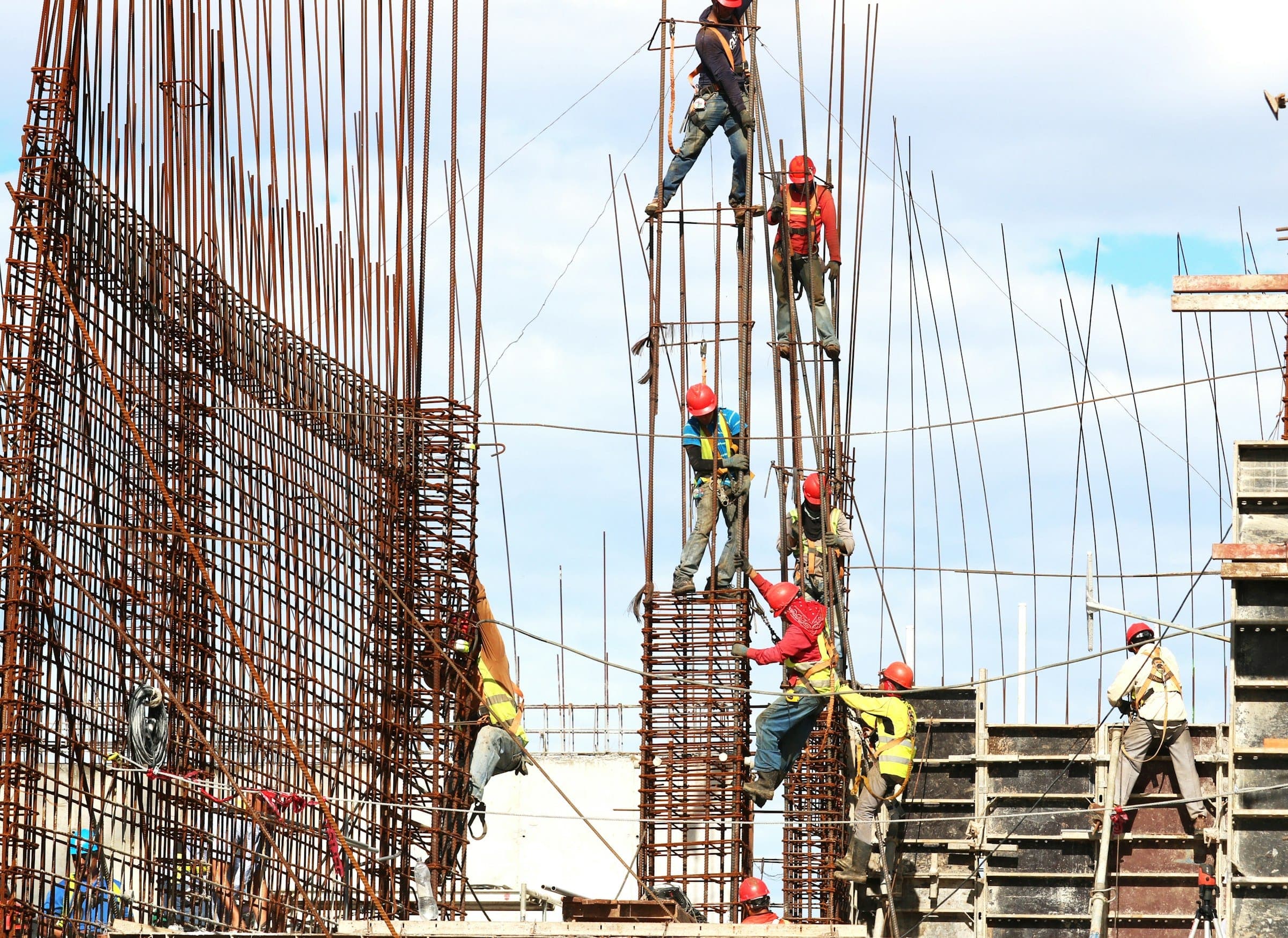
Senior team experience. Photographs are representative industry images.

Send the scope of work, the design inputs and standards that apply, and your target schedule.